


The most popular packet-based structure of layers, or protocol stack, is called the OSI model (Open System Interconnection), which was created, oddly enough by the reverse acronym, the ISO (International Organization for Standardization). It defines 7 layers. The user interface (Application Layer) is the top layer since users work directly with applications.
As you work your way down toward the lower layers, the protocols become more detailed toward the operation’s nuts and bolts. They define the details of actually preparing and moving data.
Table of Contents
Although there is officially no layer 0 or 8, they exist as the physical link (the cable) and the User, as shown below. Note how the packets get larger as each successive layer adds its own header to the packet handed down to it from the layer above.

NOTE: a unit of data at Layer 1 can be a single “bit” or a framed set of bits, depending on your interpretation. Actually, there is a frames series of bits for all layers, and this series of bits could be viewed one at a time, in which case the units of data is simply a bit. The most common telecom transmission standard is the T-carrier system (DS0, DS1or T1, DS3, or T3). It uses “frames” to transmit data, where each frame is composed of 193 bits. The 193rd bit is the framing bit used for synchronization (see Telecom 101 ).
Other Interconnection Models
Although OSI is by far the most popular – there are other models as well. Pay particular attention to the TCP/IP layered model below and how it relates to the OSI model:

![]()
The 7 Layers
Although there are seven layers in the OSI model, they can be grouped into three areas:
- High-level Protocols (layers 5, 6, and 7 – Session, Presentation, and Application)- how the data is presented, displayed, and summarized for the User – and how the User prepared data is in the reverse direction assembled into meaningful data structures (high-level protocols).
- Medium-level Protocols (Layers 3 and 4 – Network and Transport)- how the data is assembled into packets and frames and how error checking and flow control is implemented – and in the reverse direction, how the received packets and frames are assembled into structures such as files and databases (medium-level protocols).
- Low-level Protocols (Layers 1 and 2 – Physical and DataLink)- how the data is converted into electrical pulses of ones and zeroes (bits) and sent across cables or the physical medium, and in the reverse direction, how the electrical pulses are taken off the cable and converted to ones and zeroes.
The following table describes each layer:
| Application(Layer 7) | This layer supports application and end-user processes. Communication partners are identified, quality of service is identified, user authentication and privacy are considered, and any data syntax constraints are identified. Everything at this layer is application-specific. This layer provides application services for file transfers, e-mail, and other network software services. Telnet and FTP are applications that exist entirely at the application level. Tiered application architectures are part of this layer. |
| Presentation(Layer 6) | This layer provides independence from data representation differences (e.g., encryption) by translating from application to network format and vice versa. The presentation layer works to transform data into the form that the application layer can accept. This layer formats and encrypts data to be sent across a network, providing freedom from compatibility problems. It is sometimes called the syntax layer. |
| Session(Layer 5) | This layer establishes, manages, and terminates connections between applications. The session layer sets up, coordinates, and terminates conversations, exchanges, and dialogues between the applications at each end. It deals with session and connection coordination. |
| Transport(Layer 4) | Usually TCP (the top half of TCP/IP). This layer provides transparent transfer of data between end systems or hosts. It is responsible for end-to-end error recovery and flow control. It ensures complete data transfer. |
| Network(Layer 3) | Typically IP (the bottom half of TCP/IP). This layer provides switching and routing technologies, creating logical paths, known as virtual circuits, for transmitting data from node to node. Routing and forwarding are functions of this layer, as well as addressing, internetworking, error handling, congestion control, and packet sequencing. |
| Data Link(Layer 2) | Ethernet, ATM, Frame Relay, etc. At this layer, data packets are encoded and decoded into bits. It furnishes transmission protocol knowledge and management and handles errors in the physical layer, flow control, and frame synchronization. The data link layer is divided into two sublayers: The Media Access Control (MAC) layer and the Logical Link Control (LLC) layer. The MAC sublayer controls how a computer on the network gains access to the data and permission to transmit it. The LLC layer controls frame synchronization, flow control, and error checking. |
| Physical(Layer 1) | This layer conveys the bit stream – electrical impulse, light, or radio signal — through the electrical and mechanical network. It provides the hardware means of sending and receiving data on a carrier, including defining cables, cards, and physical aspects. Fast Ethernet, RS232, and ATM are protocols with physical layer components. |
![]()
OSI Model Terminology (for the units of data passed between Layers)
The Problem: the OSI model has 7 layers that communicate with one another by passing units of data. The unit of data at Layer N is called a PDU (Protocol Data Unit), and the unit of data at the layer above that (Layer N+1) is called an SDU (Service Data Unit). This is confusing since there is no single term for a unit of data.
The Solution and why it is not a good One – only high-tech folks who work with the nuts and bolts of data centers refer to these units of data as PDU’s or SDU’s. For the masses, and even most technical folks – they are most frequently called messages, and some call them packets. Unfortunately, messages and packets are also used to refer to units of data at a single layer. For example, a packet usually refers to a Layer 3 IP packet.
![]()
The Terminology
- Messages and Packets- catch-all terms used to describe any unit of data being passed between layers.
- Protocol Data Unit (PDU) and Service Data Unit (SDU): These are the actual formal terms used in the OSI Reference to describe protocol messages. A PDU at layer N is a message sent between protocols at Layer N. It consists of layer N header information and an encapsulated message from layer N+1, which is called both the layer N SDUand the layer N+1 PDU.
- Data – Layer 5, 6, and 7 – not sure why they did not differentiate between these type of data units and call them each by a different name but a good guess is that since data units at these layers are rarely discussed, apparently it was OK to called them all by the same name – simply “Data“.
- Segment – Layer 4: data units at layer 4 of the OSI model – TCP (Transmission Control Protocol).
- Packet – Layer 3: This term is considered by many to correctly refer to a message sent by protocols operating at the OSI Reference Model’s network layer. So, you will commonly see people refer to “IP packets“. However, this term is commonly also used to refer generically to any type of message, as I mentioned at the start of this topic.
- Datagram – Layer 3: This term is basically synonymous with “packet” and is also used to refer to network layer technologies. It is also often used to refer to a message that is sent at a higher level of the OSI Reference Model (more often than “packet” is).
- Frame – Layer 2: most commonly used to refer to Ethernet, Token Ring, or Frame Relay units of data. A frame gets its name from the fact that it is created by taking higher-level packets or datagrams and “framing” them with additional header information needed at the lower level.
- Cell – Layer 2: most commonly used to refer to 53-byte ATM units of data. A cell is a unit of data that is fixed in size.
- Frame – Layer 1: refers to T-Carrier Layer 1 units of data (193-bit frames).
![]()
Communication between Layers (Vertical Communication)
Moving from the top, down – messages get larger and larger. A message is passed down, and the lower layer adds a header to it. This is called encapsulation, because it is like placing an object into a capsule. The header is sometimes called a wrapper. Each successive lower layer encapsulates what it receives from the layer above it.
Moving from the bottom, up – messages get smaller and smaller. A message is first stripped of it’s header, and then the inner contents (the “data” portion) is passed up. This is “decapsulation” but no one uses that term. Each successive upper layer receives the data message from the layer below, and then strips off it’s own header and passes the data up.
![]()
OSI Model Communication between two Stations (Horizontal Communication)
Let’s consider how these corresponding layers communicate using protocols. First, recall that every layer in the model, except the bottom (physical) layer, is really a program or algorithm running on a computer. There is no way for, say, a Web browser and a Web server to actually connect together directly-they are just software programs, after all. Instead, the software running at various layers communicates logically. That is to say, through the use of software and procedures, a process running at layer 5 on one machine can accomplish logical communication with a similar process running at layer 5 on another machine.
Since machines are only physically connected at layer 1, for a protocol at layer 5 to function, the sending machine’s data must “pass down” the data through the layers between layer 5 and layer 1.The data is then transmitted over the physical connection to layer 1 of the other machine and “passed up” the receiving machine’s protocol stack to layer 5.This is how the two machines are logically linked at layer 5, even though they have no physical connection at that layer.
Thus, except for the actual physical connection at layer 1, all horizontal communication also requires vertical communication-down the stack on one machine and then back up the stack on the other. The communication doesn’t always go all the way back up the stack for each connection, however, as in the case of routing.
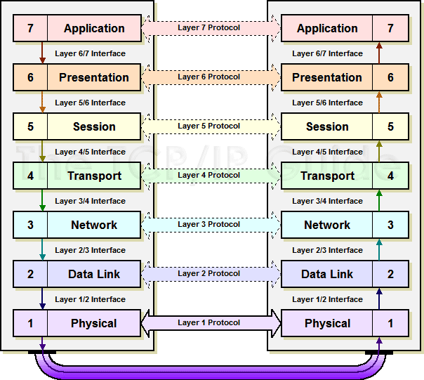
The term “protocol” has many meanings; in the context of the OSI Reference Model, it refers specifically to software or hardware elements that accomplish communication between corresponding layers on two or more devices. For example, the Internet Protocol is said to be a layer 3 protocol because each device uses IP software to communicate at layer 3. The actual transmission and reception of data only occurs at the lowest, physical layer; higher-layer protocols communicate logically, by passing data down interfaces until it reaches layer 1, transmitting at layer 1, and then passing the data back up to the appropriate layer at the recipient.
Protocols are what describe the rules that control horizontal communication, that is, conversations between processes that run at corresponding layers within the OSI Reference Model. At every layer (except Layer one) these communications ultimately take the form of some sort of message that is sent between corresponding software elements on two or more devices. Since these messages are the mechanism for communicating information between protocols, they are most generally called protocol data units (PDUs). Each PDU has a specific format that implements the features and requirements of the protocol.
Layer Services and Data Encapsulation
As we’ve already discussed in our look at protocols, the communication between layers higher than Layer one is logical; the only hardware connection is at the physical layer. Thus, in order for a protocol to communicate, it must pass down its PDU to the next lower layer for transmission. We’ve also already seen that using OSI terminology, lower layers are said to provide services to the layers immediately above them.
One of the services each layer provides is this function: to handle and manage data received from the layer above. At any particular layer N, a PDU is a complete message that implements the protocol at that layer. However, when this “layer N PDU” is passed down to layer N-1, it becomes the data that the layer N-1 protocol is supposed to service. Thus, the layer N protocol data unit (PDU) is called the layer N-1 service data unit (SDU). The job of layer N-1 is to transport this SDU, which it does in turn by placing the layer N SDU into its own PDU format, preceding the SDU with its own headers and appending footers as necessary. This process is called data encapsulation, because the entire contents of the higher-layer message are encapsulated as the data payload of the message at the lower layer.
What does layer N-1 do with its PDU? It of course passes it down to the next lower layer, where it is treated as a layer N-2 SDU. Layer N-2 creates a layer N-2 PDU containing the Layer N-1 SDU and Layer N-2’s headers and footers. And the so the process continues, all the way down to the physical layer. In the theoretical model, what you end up with is a message at layer 1 that consists of application-layer data that is encapsulated with headers and/or footers from each of layers 7 through 2 in turn, as shown below.
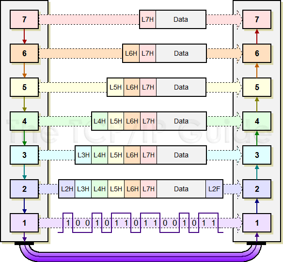
Each protocol creates a protocol data unit (PDU) for transmission that includes headers required by that protocol and data to be transmitted. This data becomes the service data unit (SDU) of the next layer below it. This diagram shows a layer 7 PDU consisting of a layer 7 header (“L7H”) and application data. When this is passed to layer 6, it becomes a layer 6 SDU. The layer 6 protocol prepends to it a layer 6 header (“L6H”) to create a layer 6 PDU, which is passed to layer 5. The encapsulation process continues all the way down to layer 2, which creates a layer 2 PDU—in this case shown with both a header and a footer—that is converted to bits and sent at layer 1.
Data Encapsulation in TCP/IP
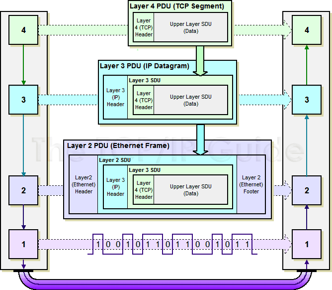
The “N-1, N-2” stuff makes this seem more difficult than it really is, so let’s use a real-world (simplified) example instead. The Transmission Control Protocol (TCP) operates at layer 4 of the OSI model. It transmits messages called segments that contain data encapsulated from higher-layer protocols. The Layer below TCP is the Internet Protocol (IP) at layer 3. It receives data from TCP and encapsulates it for transmission.
So, in the formal language of the OSI Reference Model, TCP segments are created as layer 4 PDUs. When passed to IP, they are treated as layer 3 SDUs. The IP software packages these SDUs into messages called IP packets or IP datagrams, which are Layer 3 PDUs. These are in turn passed down to a layer 2 protocol, say Ethernet, which treats IP datagrams as layer 2 SDUs, and packages them into layer 2 PDUs (Ethernet frames) which are sent on layer 1. (Actually, in some technologies further encapsulation even occurs at Layer one prior to transmission).
On the receiving device, the process of encapsulation is reversed. The Ethernet software inspects the Layer 2 PDU (Ethernet frame) and removes from it the layer 2 SDU (IP datagram) which it passes up to IP as a layer 3 PDU. The IP layer removes the layer 3 SDU (TCP segment) and passes it to TCP as a layer 4 PDU. TCP in turn continues the process, going back up the protocol layer stack. The complete process is illustrated below:
![]()


